Description
SPECIFICATIONS
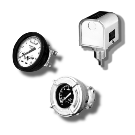
352 Liquid Level Systems
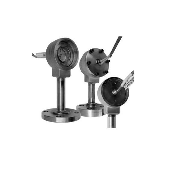
One or two enclosed detectors are linked by capillary tubing to the DPU. These devices comprise bellows that operate as “containment locks.” As stress on the bellows of the sensor differs owing to fluid density modifications, the differences are transferred hydraulically through the tubing to the bellows of the DPU. The capillary tube is versatile and simple to mount, independent of the form of the ship being fitted. Models 351, 352 and 353 can be mounted with welded (NPT), flanged or pipe coupling links and do not involve any internal plumbing of the ship. Model S048 (variation of Model 352) can be readily installed inside a ship.
The detectors are compact and lightweight and are backed by piping links or hanging brackets. If necessary, commercial elevated-face socket-weld style flanges can be adjusted to the scheme. When using dual detectors (Model 352 or 353), one detector is positioned at the edge of the reservoir and the other at the top. As stress on the reduced detector bellows varies owing to fluid density modifications, the bellows migrate, allowing the stress to be transferred hydraulically through the storage fluid in the capillary tube. The receiver then senses the stress. The sensor bellows at the bottom of the tank serves as a guide for determining inner tank temperature.
WHY Controls Supply Chain
- • Over 50 years of industry knowledge
- • Fast customer service; response within 15 minutes
- • Best price quality ratio
- • We facilitate the total procurement, purchase and engineering process of our customers
PARTS